

Embedded Systems
An embedded system is a computer designed to perform one or a few specific tasks, often with limits on power, processing speed, and memory. Many embedded systems use a microcontroller (such as an Arduino or ESP32), which combines a processor, memory, and hardware peripherals on one chip.
This page will provide an overview of core embedded systems concepts, with linked resources for diving deeper. If you have any questions, feel free to ask a peer instructor!
Digital vs. Analog Signals
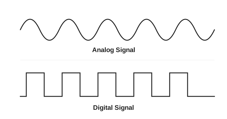
Section titled “Digital vs. Analog Signals”Digital signals have discrete states (usually 0 or 1) whereas analog signals are continuous. Microcontrollers work with both, but different hardware is needed to convert between them.
- GPIO (general-purpose input/output): Pins that can read or write a digital signals. Pull-up and pull-down resistors help keep input pins from floating when nothing is driving them.
- PWM (pulse-width modulation): Approximate an analog output with digital signals by rapidly switching a digital pin on/off (used to change things like LED brightness or motor speed).
- ADC (analog-to-digital converter): Converts analog to digital, allowing a microcontroller to read it. Many microcontrollers like the ESP32 have built-in ADCs.
- DAC (digital-to-analog converter): Converts digital to analog. Unlike PWM, a DAC can output a relatively steady voltage without relying on rapid switching and filtering.
Learn more: Digital · Analog · PWM · ADCs and DACs
Communication Protocols
Section titled “Communication Protocols”Microcontrollers often need to communicate with sensors, screens, memory chips, and other devices. Communication protocols define how they exchange data. Three common wired protocols are UART, I2C, and SPI.
| Protocol | Main signal wires | Summary |
|---|---|---|
| UART | TX, RX | Asynchronous (no common clock); both devices agree on a baud rate. TX (transmit) of device A connects to RX (receive) of device B, and vice versa |
| I2C | SDA, SCL | All devices share common SDA (serial data) and SCL (clock) lines. Devices have addresses, allowing multiple devices to communicate over the same two wires. |
| SPI | SCK, MOSI, MISO, CS | All devices share common SCK (clock), MOSI (main out, subnode in), and MISO (main in, subnode out) lines. Each peripheral has a separate CS (chip select) line to determine which device is communicating. |
All three normally require a shared ground. Out of these three, UART is the simplest, I2C is beneficial for connecting many peripherals with fewest pins, and SPI is the fastest.
Learn more: UART / Serial · I2C · SPI
Wireless Communication
Section titled “Wireless Communication”Wireless communication enables exchanging data without a physical connection. Some of the most common wireless communication protocols include:
- Wi-Fi: Useful for connecting a microcontroller to a network, sending data to a server, or hosting a webpage. In station (STA) mode, a device joins an existing network; in access point (AP) mode, it creates a network others can join.
- ESP-NOW: Espressif’s lightweight, connectionless wireless protocol for supported ESP chips. Devices can send messages directly without a Wi-Fi router, making it handy for remote controls and communication between ESP boards.
- Bluetooth Classic: Commonly used for continuous connections like audio links.
- Bluetooth Low Energy (BLE): Designed for low-power communication, especially for devices that exchange small amounts of data periodically.
Learn more: ESP32 Wi-Fi · ESP-NOW · Introduction to BLE
Interrupts and Timers
Section titled “Interrupts and Timers”Usually, a microcontroller runs instructions one after another. Interrupts let it temporarily switch to a special function, called an interrupt service routine (ISR), when something important happens. For example, a button press can trigger an interrupt instead of making your program constantly check the button.
ISRs should be short and fast. A common pattern is to set a flag in the ISR, then handle the longer operation in the main program. Avoid lengthy calculations, blocking delays, or complex library calls inside an ISR.
Hardware timers count clock ticks and can trigger events at regular intervals. They are useful for precise timing, generating PWM, and scheduling actions without depending on a long sequence of delay() calls. A prescaler slows the timer’s counting rate. A watchdog timer can reset a system if the software becomes stuck.
Learn more: Arduino Interrupts · ESP32 Hardware Timers
Threading and Real-Time Operating Systems (RTOS)
Section titled “Threading and Real-Time Operating Systems (RTOS)”Simple embedded programs often use a super loop: one loop() function repeatedly handles everything. As projects grow, it can become difficult to keep tasks responsive, especially if one task blocks the others.
A real-time operating system (RTOS) helps organize work into tasks (or threads) and decides which task runs next. On a single-core processor, tasks can take turns running so quickly that they appear simultaneous. Tasks may be running, ready, blocked (waiting), or suspended.
An RTOS also provides tools for coordinating tasks, including mutexes (protecting shared resources), semaphores (signaling or counting available resources), and queues (passing data between tasks).
Learn more: FreeRTOS Kernel Fundamentals · FreeRTOS Mutexes
Memory
Section titled “Memory”Embedded systems have limited memory, so it’s important to understand where programs and data are stored.
- RAM: Fast, volatile memory used for variables and data while the program runs. Its contents are generally lost when power is removed. The stack stores function calls and local variables; the heap is commonly used for dynamic allocations.
- Flash: Non-volatile memory that retains data without power. It often stores the program (firmware) and saved settings, but has a limited number of erase/write cycles.
- DMA (direct memory access): Allows supported peripherals or controllers to transfer data to or from memory with less direct CPU involvement. This is helpful for continuous sensor readings or high-speed data transfers.
Learn more: Arduino Memory Guide · ESP32-S3 DMA example
Memory-Mapped I/O (MMIO)
Section titled “Memory-Mapped I/O (MMIO)”Memory-mapped I/O is a way for software to control hardware by reading and writing special memory addresses called registers. For example, writing specific bits to a GPIO register might configure a pin as an output or drive it HIGH.
Arduino functions like pinMode() and digitalWrite() usually hide these low-level details. Working directly with registers can provide more control, but it requires understanding the chip’s reference manual, bit masks, and C concepts such as volatile.
Learn more: Memory-Mapped I/O in C
Power is often one of the biggest constraints in an embedded project, especially for battery-powered devices. Two useful equations are V = I x R (Ohm’s law) and P = V x I (electrical power).
A microcontroller and its peripherals must receive the correct voltage and enough current. Buck converters reduce voltage, boost converters increase voltage, and voltage regulators help maintain a stable output. Always verify a regulator’s input range, output voltage, current capacity, and wiring before connecting a board.
To save energy, a project can reduce its clock speed, turn off unused peripherals, limit wireless activity, or enter a sleep mode. On ESP32 boards, waking from deep sleep typically restarts the application, so any needed state must be stored appropriately.
Power Supply Selection
Section titled “Power Supply Selection”To determine what power setup you need, follow these steps:
-
Find the required voltage for each component via the datasheet. Some components may require different voltages.
-
Find the maximum current draw for each component via the datasheet. If all components are connected in parallel to the same voltage source, add their currents to find the total current draw.
-
Choose a power supply that provides the correct voltage and can handle the maximum current draw. It’s good practice to leave extra capacity as a safety margin. If components require different voltages, you may need voltage regulators.
-
Estimate battery runtime using the battery’s capacity and your project’s expected average power consumption:
- Using milliamp-hours:
Runtime (hours) = Capacity (mAh) / Current (mA) - Using watt-hours:
Runtime (hours) = Energy (Wh) / Power (W)
These formulas give ideal estimates. Actual runtime will generally be lower due to factors like voltage conversion losses and battery behavior. The mAh formula assumes the capacity and current are measured at the same voltage.
- Using milliamp-hours:
Remember that batteries connected in series increase voltage, while batteries connected in parallel increase capacity (mAh), assuming compatible batteries.
For example, suppose you’re building a small project with the following components:
| Component | Voltage | Current Draw |
|---|---|---|
| Microcontroller | 5V | 100 mA |
| Sensor | 5V | 25 mA |
| LEDs | 5V | 25 mA |
| Total | 5V | 150 mA |
You need a 5V power supply that can deliver at least 150 mA. If you have a battery-powered supply rated at 2,000 mAh at 5V, your estimated ideal runtime would be:
Runtime = 2,000 mAh / 150 mA ≈ 13.3 hours
In practice, runtime will be lower depending on power conversion efficiency, battery characteristics, and actual power consumption.
Learn more: Electric Power · Buck-Boost Converters · ESP32 Deep Sleep
Try It Yourself
Section titled “Try It Yourself”The best way to learn is by doing. The next sections will provide example projects to get started with hands-on learning, or feel free to build whatever you want!